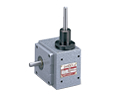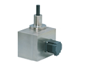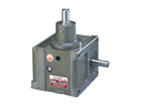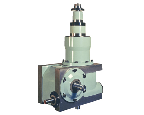
This center-column indexer was designed specifically for driving a rotary assembly chassis. It uses two worm wheels and a roller gear cam mechanism. The output has a flange for an indexing table, a stationary table mounting flange for processing units, and a continuous drive shaft in the center. Another continuous drive shaft is located under the housing for driving the processing units. This continuous drive shaft allows synchronized operation with other units, an essential requirement for any manufacturing system. As a drive source, the DA Series is particularly suitable for automatic assembly and processing machinery used for precision components, electronic device components, and small parts.
Triple Coaxial Output Design
Features a coaxial output with indexing shaft, continuous shaft, and hollow stationary shaft. Ideal for driving rotary base assembly machines.
Compact, Small Footprint
Houses the complete drive mechanism and reducer unit within the footprint of the housing.
High Accuracy
The intermittent indexing motion is produced by a roller gear cam for precision positioning.
- Assembly machine for razor blade attachments
- Assembly machine for spray nozzles
- Assembly machine for medical equipment
- Use as base chassis or main drive unit for various automated machines.
DA Series Specifications
| Input Characteristics | ||||||
| Characteristic | Symbol | Unit | 14DA | 20DA | 25DA | |
| Reducer Input Shaft | Allowable Thrust Load | C12 | N | 1078 | 980 | 1176 |
| Max Repeated Bending Force | C13 | N | 1078 | 1568 | 1960 | |
| Max Repeated Allowable Torque | C14 | N・m | 225.4 | 343 | 784 | |
| Torsional Rigidity | K8 | N・m/rad | 1.54×10⁴ | 2.55×10⁴ | 7.45×10⁴ | |
| Moment of Inertia | J2 | kg・m2 | 1.1×10⁻³ | 2.38×10⁻³ | 3.0×10⁻³ | |
| Other Information | Product Weight | kg | Approx. 160 | Approx. 395 | Approx. 585 | |
| Paint Color | Emerite Satin 5Y7/1 | |||||
| Oil Volume | L | Approx. 6 | Approx. 14 | Approx. 22 | ||
Note 1) Input moment of inertia: J is calculated in dwell.
| Output Shaft Characteristics | ||||||
| Characteristic | Symbol | Unit | 14DA | 20DA | 25DA | |
| Cam Shaft | Allowable Thrust Load | C9 | N | 2940 | 4900 | 5782 |
| Max Repeated Bending Force | C10 | N | 3675 | 7546 | 8722 | |
| Max Repeated Allowable Torque | C11 | N・m | 588 | 1274 | 1764 | |
| Torsional Rigidity | K6 | N・m/rad | 1.37×10⁵ | 2.65×10⁵ | 4.31×10⁵ | |
| Moment of inertia (Note 1) | J1 | kg・m2 | 4.5×10⁻² | 0.116 | 0.565 | |
| Continuous Shaft | Allowable Thrust Load | C1 | N | 1470 | 2940 | 3430 |
| Allowable radial load | C2 | N | 2548 | 7840 | 11760 | |
| Max Repeated Allowable Torque | C3 | N・m | 274.4 | 1274 | 1960 | |
| Torsional Rigidity | K1 | N・m/rad | 1.04×10⁴ | 8.82×10⁴ | 2.94×10⁵ | |
| Inertia Moment | J3 | kg・m2 | 1.05×10⁻² | 2.5×10⁻² | 7.75×10⁻² | |
| Fixed Shaft | Allowable Thrust Load | C4 | N | 8134 | 13720 | 18620 |
| Allowable radial load | C5 | N | 3822 | 8820 | 14700 | |
| Max Repeated Allowable Torque | C6 | N・m | 980 | 1960 | 2254 | |
| Torsional Rigidity | K3 | N・m/rad | 1.37×10⁵ | 3.53×10⁵ | 4.61×10⁵ | |
| Intermittent Rotary Shaft | Allowable Thrust Load | C7 | N | 9800 | 15680 | 16660 |
| Allowable Radial Load | C8 | N | 15680 | 28420 | 36260 | |
| Allowable Torque | TS | N・m | Refer to Torque Transfer Table | |||
| Torsional Rigidity | K4 | N・m/rad | 8.13×10⁵ | 5.88×10⁶ | 4.9×10⁶ | |
| Inertia Moment | J0 | kg・m2 | 9.4×10⁻² | 0.515 | 1.10 | |
| Indexing Accuracy | Seconds | ±30 | ±30 | ±20 | ||
(1N ≒ 0.102 kgf)