

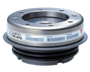
This TorqueLimiter is designed to be used between two shafts for protection against overloads only in the rotating direction. It offers excellent rigidity in the rotating direction. It also serves as a coupling by absorbing misalignment between two clamping elements. 
High Accuracy
Excellent trip torque accuracy
Easy to Adjust
Trip torque can be adjusted by simply turning the adjustment nut.
No Play
Zero backlash
Coupling Function
Also comes with the ability to function as a coupling between two clamping elements.
| Characteristics | Unit | 4TC | 5TC | 6TC | 7TC | 8TC | 11TC | 14TC | 18TC | |
| Trip Torque Adjustment Range | N・m | 0.3 to 4.5 | 0.8 to 18.0 | 2 to 50 | 20 to 350 | 40 to 450 | 70 to 1000 | 100 to 2000 | 700 to 5000 | |
| Torque Adjustment Nut Thread Pitch | mm | 1 | 1.5 | 1.5 | 2 | 2 | 2 | 2 | 3 | |
| Max Allowable Deflection | deg | 1 | 1 | 1.5 | 1.2 | 1.2 | 1 | 0.7 | 0.5 | |
| Max Allowable Clearance Error | mm | ±1.0 | ±1.0 | ±1.5 | ±1.8 | ±2.0 | ±2.5 | ±3.5 | ±3.5 | |
| Max Allowable Parallelism Error | mm | 0.05 | 0.05 | 0.05 | 0.1 | 0.1 | 0.1 | 0.1 | 0.1 | |
| Max Allowable Rotation Speed | rpm | 2000 | 1600 | 1000 | 700 | 500 | 400 | 300 | 200 | |
| Moment of Inertia | kg・m2 | 0.9×10⁻⁴ | 4.0×10⁻⁴ | 1.7×10⁻³ | 5.8×10⁻³ | 1.4×10⁻² | 3.5×10⁻² | 9.3×10⁻² | 0.4 | |
| Mass | kg | 0.25 | 0.68 | 1.5 | 3.2 | 5.3 | 10.8 | 20 | 45 | |
| Shaft Bore Shape (Shaft Diameter) |
A | mm | 10 to 15 | 12 to 22 | 15 to 30 | 20 to 40 | 30 to 50 | 40 to 60 | 50 to 60 | 60 to 80 |
| B | mm | - | 15 to 20 | 15 to 25 | 20 to 35 | 30 to 50 | 40 to 60 | 50 to 60 | 60 to 90 | |
| C | mm | - | - | 16 to 25 | 20 to 35 | 30 to 45 | 35 to 60 | 50 to 60 | 60 to 90 | |
| D | mm | - | - | - | - | - | - | - | - | |
| E | mm | - | - | - | - | - | - | - | - | |
| F | mm | - | - | 16 to 22 | 20 to 35 | 30 to 45 | 35 to 60 | 50 to 60 | 60 to 90 | |
* Product specifications and dimensions are subject to change without notice. Confirm details when ordering.