Products

Features
The TorqueLimiter is a mechanical
overload safety device that offers
easy torque control and a precise
trip and reset mechanism.
Accurate Transfer of Torque
Faithfully transfers the rotation characteristics from the input to the output. Displays the same properties in either forward or reverse direction.
Accurate Actuation
Activates accurately at the torque setting, with virtually no variation when repeatedly activated.
No Backlash, High Rigidity
The torque transmission path is held under constant stress to eliminate rotational backlash and provide strong rigidity.
Simple Torque Adjustment
The torque can be adjusted over a broad range, and can also be fine tuned within a more precise range. These adjustments are easy to perform even after the TorqueLimiter has been installed.
One-point Setting
The one-point setting feature ensures the TorqueLimiter resets precisely to the origin after tripping. This is particularly useful for machines that must be kept in synchronization.
Detection of Overloads
When an overload occurs, the torque plate moves toward the pressure nut. This displacement can be detected with a limit switch to generate an overload signal. This plate moves without changing the spatial position of the drive boss or hub, to prevent any connected table or pulley from sliding.
Easy to Handle
Easy to install and remove without the use of special tools. All characteristics are stable against ambient conditions, such as temperature and humidity.
Available in a Variety of Types
TorqueLimiters are used in a variety of industries. Many design variations are available to meet a wide range of requests. Users can choose from a wide selection of 8 models and 37 types.
Product Lineup
Sankyo TorqueLimiters are high-performance overload safety devices based on a mechanical tripping mechanism that is activated when excessive torque occurs. The product line consists of flange types for direct mounting on tables, pulleys, and arms; coupling types for coupling two shafts with the ability to absorb misalignment, and linear types for use on reciprocating linear motion parts. Each type meets the requirements expected of safety devices for automated machinery, and have become the preferred choice in a wide range of industrial fields.
Sizing Tips
TorqueLimiters are safety devices used to protect against torque overloads. They are designed to be used for shutting off torque, or tripping, when excessive torque occurs between two mechanical elements. The TorqueLimiter should be attached as close as possible to the end of the final output on the machine to be protected. It is also important to select the model and size that best suits the machine to protect, such as mounting surface, application, and usage conditions.
Items to Consider
(1) Usage
a. Safety device b. Clutch c. Torque control
d. To release torque e. Coupling f. Torque activated device

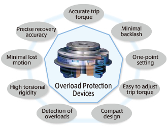
(2) Performance Requirements
Issues to consider: torque setting range, accuracy of the torque setting, resetting accuracy, whether automatic reset is desired, no backlash, rigidity, minimal lost motion, overload detection, activation frequency, mounting, coupling (correction of misalignment caused by errors in parallelism, angularity, or clearance), reset method, etc.

(3) Load Characteristics
Issues to consider: does the load fluctuate, is it caused by positive or negative loads, is it irregular, does it come from vibration, moment, does it occur in the radial or thrust directions, or due to gravity.

(4) Drive Conditions
Issues to consider: what kind of drive is being used ? a motor (AC, DC, hydraulic motor, etc.), will it have a clutch/brake, what kind of transmission element will it use (V-belt, timing belt, chain, gears, cams, etc.).

(5) Operating Environment
Issues to consider: ambient conditions such as temperature, humidity, dust, etc., is the environment subject to water droplets, oils, and chemicals, and is there ventilation.

Sizing Procedure
1. Determine Type
・ Flange Type
Choose this type if the TorqueLimiter is to be mounted directly on the table or arm, or on the element that will transfer rotation, such as a gear or sprocket.
・ Coupling Type
Choose this type to mate two shafts. ・ Linear Type
↓
2. Determine Model Number
Usage Conditions Mounting style of TorqueLimiter (shaft, flange, ring, surface)
Recovery method (automatic, manual/release type)
Torque control method (springs, air)
Recovery position (one-point, two-point, multiple)
↓
3. Trip Torque Calculation
Calculate the load torque from the machine's accuracy, durability, and load conditions. Then, apply a service factor based on the operating conditions and model to determine the threshold torque that must not be exceeded.
↓
4. Sizing
Compare the trip torque and the torque adjustment range of each size to determine the proper size, taking into consideration the mounting style and allowable speed.
LM
TF TF-C TNF TRF TAD To TC TC-C TR LM
Feel free to download our catalogs or make an inquiry.
Downloads
Catalogs and Inquiries
top