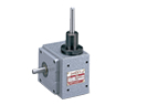
The F series is our high-end pick & place unit. It is driven by two independent roller gear cams. The use of a separate lift cam and oscillating or indexing cam gives the unit excellent rigidity, while allowing for flexible timing schemes.
Extremely Flexible Design
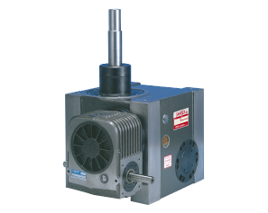
Max lift: 80 mm, Max oscillating angle: 90°
Extremely Rigid, Solid Motion
Uses two roller gear cams for solid, stable motions.
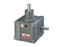
Flexible Mounting Positions
Index mounts in any position with gearmotor mounting on either side of the index.
- Transfer mechanism in manufacturing equipment for automotive parts
- Conveying mechanism in food container and coating equipment
- Conveying mechanism for various automatic machinery
8F Torque Transfer Capacity Table (Oscillating Handlers)
| Oscillating Angle ψ (deg) |
Index Period θ0 (deg) |
Static Load Ts (N・m) |
Dynamic Load To (N・m) Input Speed N (rpm) |
Input Shaft Friction Torque Tx (N・m) |
||||
| 20 | 30 | 40 | 50 | 60 | ||||
| 15 | 35 | 182.3 | 86.2 | 76.4 | 70.6 | 65.7 | 62.7 | 24.5 |
| 45 | 241.1 | 111.7 | 99.0 | 91.1 | 85.3 | 80.4 | ||
| 60 | 259.7 | 110.7 | 98.0 | 90.2 | 84.3 | 79.4 | ||
| 30 | 55 | 161.7 | 66.6 | 59.8 | 54.9 | 51.0 | 48.0 | |
| 75 | 225.4 | 90.2 | 79.4 | 72.5 | 68.6 | 64.7 | ||
| 90 | 241.1 | 91.1 | 80.4 | 73.5 | 68.6 | 65.7 | ||
| 45 | 75 | 152.9 | 57.8 | 51.0 | 47.0 | 44.1 | 41.2 | |
| 90 | 203.8 | 76.4 | 67.6 | 62.7 | 58.8 | 54.9 | ||
| 100 | 214.6 | 78.4 | 69.6 | 63.7 | 59.8 | 56.8 | ||
| 60 | 100 | 184.2 | 67.6 | 59.8 | 54.9 | 51.0 | 48.0 | |
| 110 | 195.0 | 68.6 | 60.8 | 55.9 | 52.9 | 50.0 | ||
| 120 | 203.8 | 70.6 | 62.7 | 56.8 | 53.9 | 51.0 | ||
| 90 | 110 | 124.5 | 42.1 | 38.2 | 34.3 | 32.3 | 30.4 | |
| 120 | 132.3 | 44.1 | 39.2 | 36.3 | 33.3 | 31.4 | ||
| 135 | 143.1 | 46.1 | 41.2 | 37.2 | 35.3 | 33.3 | ||
8F Carrying Capacity Table
| Lift LT (mm) |
Index Period θ0 (deg) |
Dynamic Allowable Load Wo(N) Input Speed N (rpm) |
||||
| 20 | 30 | 40 | 50 | 60 | ||
| 20 | 23 | 215.6 | 168.6 | 99.0 | 52.9 | 22.5 |
| 40 | 294.0 | 294.0 | 294.0 | 269.5 | 206.8 | |
| 25 | 25 | 205.8 | 159.7 | 91.1 | 47.0 | 17.6 |
| 40 | 294.0 | 294.0 | 294.0 | 229.3 | 169.5 | |
| 30 | 30 | 221.5 | 176.4 | 107.8 | 60.8 | 28.4 |
| 47 | 294.0 | 294.0 | 294.0 | 247.0 | 186.2 | |
| 35 | 35 | 234.2 | 190.1 | 121.5 | 73.5 | 39.2 |
| 45 | 294.0 | 294.0 | 280.3 | 204.8 | 148.0 | |
| 40 | 40 | 245.0 | 201.9 | 133.3 | 84.3 | 49.0 |
| 54 | 294.0 | 294.0 | 294.0 | 236.2 | 177.4 | |
| 45 | 45 | 253.8 | 210.7 | 143.1 | 94.1 | 57.8 |
| 55 | 294.0 | 294.0 | 294.0 | 219.5 | 162.7 | |
| 50 | 50 | 294.0 | 294.0 | 241.1 | 170.5 | 118.6 |
| 65 | 294.0 | 294.0 | 294.0 | 251.9 | 193.1 | |
11F Torque Transfer Capacity Table (Oscillating Handlers)
| Oscillating Angle ψ (deg) |
Index Period θ0 (deg) |
Static Load Ts (N・m) |
Dynamic Load To (N・m) Input Speed N (rpm) |
Input Shaft Friction Torque Tx (N・m) |
||||
| 20 | 30 | 40 | 50 | 60 | ||||
| 15 | 25 | 236.2 | 113.7 | 100.9 | 92.1 | 86.2 | 81.3 | 24.5 |
| 35 | 333.2 | 170.5 | 150.9 | 138.2 | 129.4 | 122.5 | ||
| 45 | 333.2 | 164.6 | 146.0 | 134.3 | 125.4 | 118.6 | ||
| 30 | 35 | 203.8 | 88.2 | 78.4 | 71.5 | 67.6 | 63.7 | |
| 45 | 326.3 | 139.2 | 123.5 | 112.7 | 105.8 | 100.0 | ||
| 60 | 333.2 | 140.1 | 123.5 | 113.7 | 105.8 | 100.9 | ||
| 45 | 50 | 198.9 | 77.4 | 68.6 | 62.7 | 58.8 | 55.9 | |
| 65 | 322.4 | 122.5 | 108.8 | 100.0 | 93.1 | 88.2 | ||
| 75 | 333.2 | 124.5 | 109.8 | 100.9 | 94.1 | 89.2 | ||
| 60 | 65 | 196.0 | 70.6 | 62.7 | 57.8 | 53.9 | 51.0 | |
| 90 | 326.3 | 112.7 | 100.0 | 92.1 | 86.2 | 81.3 | ||
| 100 | 333.2 | 113.7 | 100.9 | 92.1 | 86.2 | 82.3 | ||
| 90 | 97 | 196.0 | 63.7 | 56.8 | 51.9 | 48.0 | 46.1 | |
| 115 | 212.7 | 65.7 | 58.8 | 53.9 | 50.0 | 47.0 | ||
| 125 | 221.5 | 66.6 | 58.8 | 53.9 | 51.0 | 48.0 | ||
11F Carrying Capacity Table
| Lift LT (mm) |
Index Period θ0 (deg) |
Dynamic Allowable Load Wo(N) Input Speed N (rpm) |
||||
| 20 | 30 | 40 | 50 | 60 | ||
| 20 | 23 | 323.4 | 250.9 | 143.1 | 72.5 | |
| 30 | 392.0 | 333.2 | 224.4 | 145.0 | 87.2 | |
| 40 | 392.0 | 392.0 | 392.0 | 384.2 | 291.1 | |
| 30 | 28 | 312.6 | 241.1 | 136.2 | 66.6 | |
| 35 | 380.2 | 312.6 | 204.8 | 127.4 | 71.5 | |
| 45 | 392.0 | 392.0 | 392.0 | 344.0 | 252.8 | |
| 40 | 32 | 299.9 | 230.3 | 128.4 | 60.8 | |
| 40 | 370.4 | 302.8 | 197.0 | 120.5 | 66.6 | |
| 50 | 392.0 | 392.0 | 392.0 | 323.4 | 234.2 | |
| 50 | 36 | 294.0 | 226.4 | 125.4 | 58.8 | |
| 45 | 365.5 | 298.9 | 195.0 | 119.6 | 65.7 | |
| 55 | 392.0 | 392.0 | 392.0 | 311.6 | 224.4 | |
| 60 | 40 | 292.0 | 225.4 | 125.4 | 59.8 | |
| 50 | 362.6 | 297.9 | 195.0 | 120.5 | 66.6 | |
| 60 | 392.0 | 392.0 | 392.0 | 305.8 | 219.5 | |
| 70 | 43 | 284.2 | 218.5 | 120.5 | 55.9 | |
| 55 | 362.6 | 298.9 | 197.0 | 123.5 | 69.6 | |
| 65 | 392.0 | 392.0 | 392.0 | 303.8 | 217.6 | |
| 80 | 46 | 278.3 | 213.6 | 117.6 | 53.9 | |
| 60 | 363.6 | 300.9 | 199.9 | 126.4 | 72.5 | |
| 70 | 392.0 | 392.0 | 392.0 | 302.8 | 217.6 | |